For use with a motor lock (that has 0 resistance between signal cables when locked, and infinite resistance when unlocked) the charge controller lock outputs are configured as follows:
- B – signal. If the motor is locked +12V is expected, if it is in unlocked state, 0V is expected.
- R and W – Locking of motor is powered through these outputs for locking and unlocking. Locking is done with 600ms pulse. If it is detected that the motor has not functioned, the locking/unlocking action is repeated after 5 seconds. If the locking action is reverse, the wires should be swapped between R and W connections.
Connection of another motor:
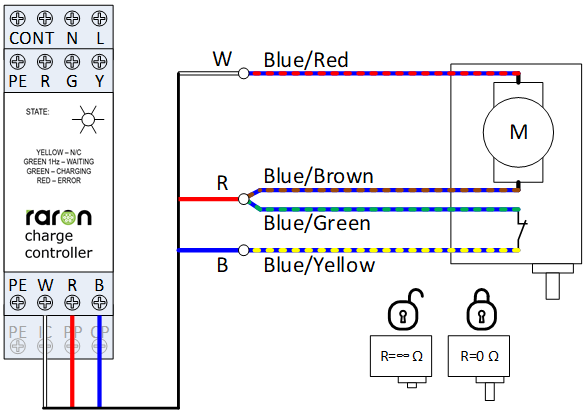
There can be different colour codes for the wires of locking motors, therefore it is advised to consult the datasheet of the manufacturer. The connections can also be determined using a multimeter.