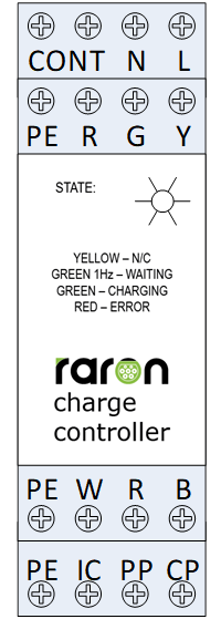
The following table presents the descriptions of the terminals of the RARON charge controller. The descriptions apply to all versions of the controller, except for terminals B, R and W for which the operation depends on the controller version.
| Terminal | Description |
| L | Connects to AC “live” or “line” with 90-264V AC @ 47-63 Hz |
| N | Connects to AC “neutral” line with 90-264V AC @ 47-63 Hz |
| Contactor | Two connectors. Connects to 230V spool connection of the contactor, usually marked as A1 and A2. WARNING! Selecting a contactor with incorrect power or voltage rating can lead to damage of the charge controller, personal injury or fire. |
| PE | Connects to ground connection of the electricity supply or earth connection. |
| Y, G and R | Protected connection for yellow (Y), green (G) and red (R) LED. Connects to anode (+) pole of LED. The cathode of LED should be connected to PE. |
| B | Solenoid or motor signal connection.[1] |
| R | Solenoid or motor power connection.1 |
| W | Solenoid or motor power connection.1 |
| CP | Control Pin. Connects to the CP of IEC61851/J1772 EVSE socket/plug. |
| PP | Proximity Pin. Connects to the PP of IEC61851 EVSE socket. |
| IC | Input Current. Connects to input current limit selecting resistor, switch or dial. Input current limit resistor values are listed further in the document. |
[1] For details on use with solenoid or motor lock please see section “Use with a socket”.